August 28, 2017
Rebuilders Rally to Crack the Code: Converter Identification
Ed Lee
A torque converter is like a box of chocolates. You never know what you’re going to find. Until now.
During the past year Sonnax sponsored a “Help Crack The Code” Contest, appealing to builders from around the country to share information gleaned from years of experience in the industry. Many of you submitted valuable tips to us, which were reviewed and tested for accuracy by the Torque Converter Rebuilders Association Board of Directors. Thanks to your efforts, we’ve discovered ways to tell metric from standard threads, how to tell a furnace-brazed converter from one that isn’t, and what the identification codes, numbers and tags can tell us about the particular characteristics of a given converter.
Metric vs. Standard
Do you know how to tell the difference between a GM TH400-style converter with metric threads in the mounting pads from one with standard threads – without checking the threads? We didn’t either, but Gary Rogers at Robert T. Holt & Sons in Mount Pleasant, Texas, showed us how.
 |  |
His secret (also GM’s secret for many years) is this: There’s an identification groove just above the welds that attach the mounting pads to the cover on all TH0400-style torque converters with metric threads. (See Figure 1). A typical converter with standard threads will look like Figure 2.
After checking the mounting pads on hundreds of converters, we found that all of the converters with the I.D. groove did, in fact, have metric threads. (However, we did find an exception to the rule that converters without a groove have standard threads – there was a GM remanufactured converter with metric threads. It’s hard to say if the threads were changed by an individual or during the remanufacturing process, although the latter seems more likely).
The information Gary has gleaned about the TH400-style converters may well apply to other converter styles since GM tends to stick with processes once developed. His tip may help someone else solve yet another piece of the puzzle.
Furnace-brazed or Not?
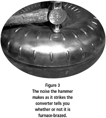
OE manufacturers are furnace-brazing more of their converters to meet increasing torque load demand, and it’s critical to be able to identify them. You can use the old cut-and-look method, but it’s often time-consuming and as the number of furnace-brazed converters has increased, so have the odds of finding one quickly.
Dacco’s latest catalog includes some handy furnace braze information in the 298mm section. If you can see the I.D. code on your converter, the second digit will allow you to determine both the stall of the converter and whether it is furnace-brazed. This I.D. method works well on most late-model GM 298mm converters. It’s a good bet that if the second letter of the code is a C, H, K or L, your converter will have a furnace-brazed impeller. You may also notice that on the late-model 298mm converters, the majority of the I.D. stickers in a solid color will have a furnace-brazed impeller and the majority of the stickers with stripes won’t. Unfortunately, neither is foolproof enough to use as an identification process.
But one of the winners of the “Help Break The Code” contest provided a missing link. Jesse Campbell from the Colorado Converter Co. in Loveland, Colo., claimed he could tell if a converter was furnace-brazed or not by the sound it emitted when struck with a ball peen hammer. He was right.
Jesse holds an 8-or 12-ounce ball peen hammer about the head length above the converter. Holding the handle loosely, he lets the hammer fall. The hammer strikes the converter between the two dimples, on the middle row of dimples, on the impeller side of the converter (see Figure 3). A dull muffled sound tells him the converter is not furnace-brazed. A furnace-brazed converter has a crisper, sharper ringing sound.
Now, transmission shops have been using this trick for years to tell if GM 700 pump rings were hardened or not. With a little bit of practice anyone can become proficient at finding the furnace-brazed core.
One word of caution: With the possible exception of some late-model Ford AODE/4R70W converters, the Ford 12” impeller was never furnace-brazed. When you are mastering Jesse’s ball peen method, you’ll find some Ford C6 or AOD converters emit a sound similar to a furnace-brazed impeller. What you’re hearing is not an exception to the furnace-brazed rule, but a way to tell if the vanes are tight in the 12” Ford impeller. An impeller with good tight vanes will emit a dull muffled sound, just as you would expect. What you would not expect is that the looser the vanes, the more similar the sound is to that of a furnace-brazed impeller. This is a win-win situation. Not only can you tell if an impeller is furnace-brazed or not, you can also tell how tight the vanes are.
 |
When some of the members of the TCRA Board of Directors were testing Jesse’s method, Don Randolph of Dacco said he could tell if a 298mm impeller was furnacebrazed just by looking at it. Don went on to correctly identify six out of six converters.
Don explained that the vane helps strengthen the impeller. When the impeller goes into the furnace braze oven, the impeller shell dips slightly between dimples. An impeller that has not been in an oven will be straight across between the dimples (see Figures 4 and 5).

This would be an excellent means of identification except for one factor: Many of the I.D. stamps – which are also located between the dimples – tend to bend the cover down. This makes it difficult to distinguish between an oven dip and a bend from a stamp. But you can be sure that all of the converters that do not dip between the dimples will not be furnace-brazed.
A Question of Friction
Every converter builder knows there are three different types of friction material to choose among: paper, carbon and woven 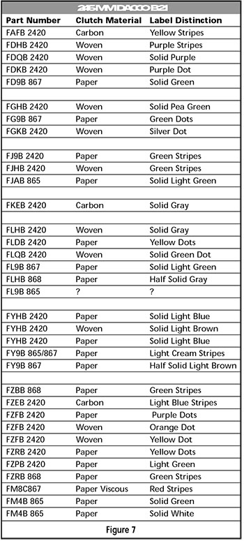 graphite. Each one of these friction materials has its own unique properties and specific uses, making it important to be able to identify the correct material needed for each application. But it hasn’t been easy.
 graphite. Each one of these friction materials has its own unique properties and specific uses, making it important to be able to identify the correct material needed for each application. But it hasn’t been easy.
The GM converters have proven particularly problematic. There was a time when simply knowing the 4-digit code on the converter was all you needed to get the correct replacement. Those days are gone. Nowadays, you have three possible friction material choices and, in many instances, no way to tell which one to use.
Jim Currier Jr. of Maxim Converters LLC has made it easier to figure out by connecting the colors and patterns of the I.D. stickers with the I.D. codes. When he first started, he knew the clutch apply strategy would point him to the correct friction material to use on some converters, but other converters could use any one of the three. This dilemma was especially problematic when it came to the 245mm GM B21, particularly on the FLHB converter.
Jim began to notice subtle differences in the colors and patterns of the colors on the I.D. stickers of converters with the same I.D. code. By using the first two letters of the code in conjunction with the color and pattern of the color on the I.D. tag, he was able to I.D. the friction material used in nearly all converters – until he found an FJ9B converter with green diagonal stripes with a paper lining, and a FJHB converter with green diagonal stripes with a woven graphite lining. At this point, he added the third and fourth digits of the code to his I.D. decoding process. He was soon able to say with certainty that a FYHB converter with a solid pattern/light blue tag would have paper friction material on the clutch and the same FYHB code with a solid pattern/light brown tag would have woven graphite friction material on the clutch (see Figure 6). Jim continues to have good success with this system today, provided the I.D. tag is present.
Five of the patterns for the late model B21 converters are listed here, along with the codes and colors and the friction material that they identify (see Figure 7). Please note that many of the early B21 patterns that were only used on the TH125 lockup converters have been left out because they all had paper linings.
More Deciphering
The FLHB converters were also causing headaches for Jeff Lehmann and Bill Spratt at Precision Converters of Ohio. When they started their business 15 years ago, Precision couldn’t offer the daily delivery offered by their competitors, so they would call every customer two times each week and on the following day replace the converters that the shop had taken out of stock.
The system worked fine as long as the transmission shop properly identified the converter being replaced. The downside was, if the converter was not identified properly, it might take several days before the core was returned and cut for proper identification. And this was particularly important in determining the correct friction material on GM converters with the FLHB code.
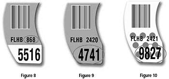
They knew there was a good chance that FLHB converters with the early part numbers (the seven-digit part number that started with 86) would have paper linings (see Figure 8). But any identification beyond the early paper was just a guess. In 1998 Jeff and Bill started noticing that all of the FLHB converters with the large four-digit number 4741 on the I.D. tag had woven graphite friction material on the clutch (see Figure 9).

This heightened awareness of the large four-digit number allowed them to identify a second number that was also found exclusively on converters with woven graphite linings. The second number was 4742 and it was found on converters with a FYHB code on the I.D. tag. Soon they had expanded their I.D. system to cover as many converters as possible. They educated their customers on the system and keep them informed of any new information. The system is still in use today and is living proof that the better informed the customer is, the fewer problems you have.
Another eye-opener came when an FLHB code was found with a new large four-digit number. This new number was 9827 (see Figure 10). This converter was very similar to the FLHB converter with the 4741 number, except that it had a 21-vane stator. The converters with the FLHB code historically have a 14-vane stator. It’s very uncharacteristic for GM to use a different stator in a converter with the same code. The good news is that this FLHB converter with the 21-vane stator has a different large four-digit number. Is it possible that the stator can also be identified by this number? This information also raises questions about the identification of other components of the converter by the large four digit number.
After much research and long hours the TCRA Board has compiled as complete a list as possible of the information learned about the four-digit number (see Figure 11). The list will undoubtedly continue to grow for some time.
 |
In the meantime, our thanks to Gary Rogers, Jesse Campbell, Jim Currier Jr., Jeff Lehmann and Bill Spratt for taking the time to do the research, and for sharing the knowledge they have learned. They wholeheartedly deserve to be the winners of the Sonnax “Help Break the Code” contest.
Ed Lee is a Sonnax Technical Specialist who writes on issues of interest to torque converter rebuilders. Sonnax supports the Torque Converter Rebuilders Association.
Learn More
Related Units
TH400 (3L80), AT-540 Converter
AODE, 4R70W, 4R75W Converter
AOD (FIOD) Converter
C4, C6, FMX 12", C4 11-1/4" Converter
298mm LU (TH250C, TH350C, 200-4R, 4L60 & E) Converter
Related Parts
Required
Recommended
280mm LU (4L60-E) “VJCX” • 298mm LU (TH250C, TH350C, 200-4R, 4L60 & E) • 300mm (4L60-E)
Friction Ring S20250WC
- Material: WC
- Outer Dia.: 11.125"
- Inner Dia.: 10.000"
- Thickness: 0.020"
Required
Recommended
245mm LU Euro (5L40-E) • 258mm LU (4L60-E, 5L40-E) • 258mm LU (4T65-E) • 4L60-E (298mm), Single-Plate Performance Converter • 4L60-E (300mm), Single-Plate Performance Converter • 6L80 (245mm), Single-Plate Performance Converter
Friction Ring S20300WC
- Material: WC
- Outer Dia.: 9.500"
- Inner Dia.: 8.250"
- Thickness: 0.020"
Required
Recommended
245mm LU (3T40, 3L30, TH200C, 4T60-E, 4L60 & E:S-10 only) • 4L60 (700-R4), 4L60-E, 200-4R (298mm), Single Plate Performance Converter (Mounting Ring) • 4L60-E (300mm), Single-Plate Performance Converter (Mounting Ring) • 4L80-E, 4L85-E, Single-Plate Performance Converter (Mounting Ring) • AODE, 4R70W Performance Converter
Friction Ring S20320WC
- Material: WC
- Outer Dia.: 9.000"
- Inner Dia.: 7.750"
- Thickness: 0.020"
Required
Recommended
6T40/6T45, 236mm
Friction Ring S20680WC
- Material: WC
- Outer Dia.: 9.813"
- Inner Dia.: 8.562"
- Thickness: 0.020"
Required
Recommended
6L80, 6L90 (300mm)
Friction Ring S20750WC
- Material: WC
- Outer Dia.: 11.120"
- Inner Dia.: 9.840"
- Thickness: 0.020"
Required
Recommended
6F50/6F55 • 6T70, 6T75
Friction Ring S20930WC
- Material: WC
- Outer Dia.: 10.200"
- Inner Dia.: 9.200"
- Thickness: 0.020"
Required
Recommended
6L90 (Captive Clutch)
Friction Ring S20960WC
- Material: WC
- Outer Dia.: 10.170"
- Inner Dia.: 9.055"
- Thickness: 0.020"
While Sonnax makes every effort to ensure the accuracy of technical articles at time of publication, we assume no liability for inaccuracies or for information which may become outdated or obsolete over time.
