February 26, 2021
700-R4 (4L60) Performance Transmission Build Guide
Gregg Nader
Burnt 3-4 clutch packs are notoriously common in the GM 4L60/E family of transmissions. Tech hotlines and internet bulletin boards are often jammed-up with people pleading for help with this 3-4 roasting. Some technicians get frustrated and throw multiple Hail Mary replacement parts at the transmission when facing this issue. But it doesn’t have to be an exercise in frustration; burnt 3-4 clutches can be transformed from a dreaded problem into a routine money maker.
Since the cause of 3-4 burnup can be due to a single failed component or a combination of leaks, the repair that worked last time won’t necessarily work this time — or the next. Compounding the difficulty of diagnosing the original burnup is the fact that it is easy to induce new causes for failure during repair/rebuild. Cracking a pump cover during stator shaft installation or compromising an input shaft seal are common, self-inflicted wounds that lead to smoked clutches. We see the 3-4 burnup issue frequently, but finding the root cause can often be elusive.
All it takes to successfully stare down 3-4 slip and burn — and the anxiety that comes with it — is a good map and a plan to follow. With an understanding of the circuits and components involved, a solid inspection and testing routine that covers all the bases can be adopted. Relying on this routine each time you encounter burnt 3-4 clutches will give you the peace of mind that comes from knowing you addressed all the problem areas and a comeback is not likely.
Low line pressure and/or leaks of 3rd Gear oil are the root cause of most 3-4 slipping. The 3-4 hydraulic circuit is quite long; it is interconnected to D4, Forward clutch, 2nd, 2nd clutch and 3rd accumulator circuits. Since any pressure change in one part of the circuit affects the rest of the circuit, even small leaks at a few junctions along the way can add up to a big enough pressure loss to allow slipping.
Even if the 3-4 circuit is working perfectly, low or unstable line pressure (and AFL pressure, which affects line pressure) can cause slipping and burning. Like 3-4 clutch oil, AFL and line pressure circuits have common leak points. Any time a burnt clutch pack is found, all three circuits must be inspected methodically to discover and eliminate all the leaks — big and small. The presence of an obvious leak, such as a cracked apply piston, should not stop you from investigating further.
There is a raft of common leak points to inspect; following a path that addresses them all is our goal. Remember: While checking these areas for leaks, we must also be sensitive to various mechanical and electrical considerations as well. Use the following checklist as a convenient guide for hunting down and eliminating 3-4 clutch problems.
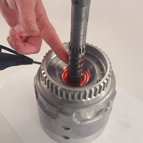
| Figure 1 — Air Checking Input Housing Bore-to-Shaft |
|---|
 |
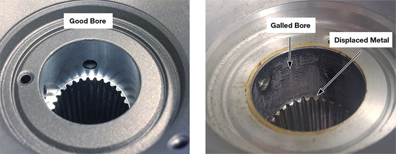
| Figure 2 — Housing Shaft Bore: Good vs. Galled |
|---|
 |
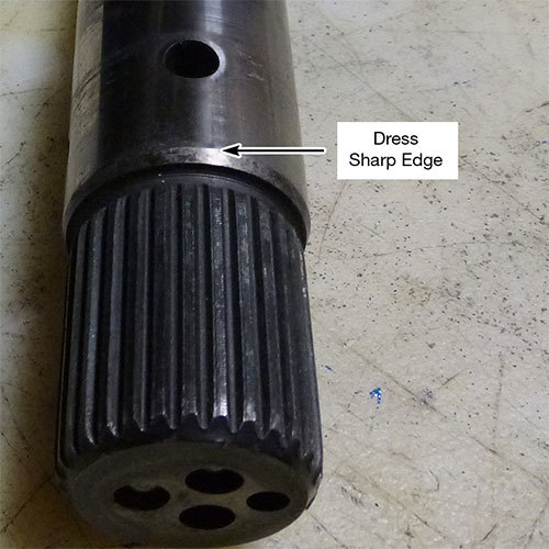
| Figure 3 — Prevent future leaks by properly prepping the input shaft press area. |
|---|
 |
Is this tech helpful? Provide us with your feedback at the end of the article.
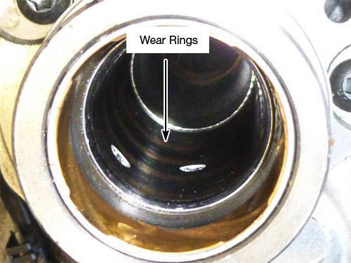
| Figure 4 — Check for wear inside the stator sleeve. |
|---|
 |
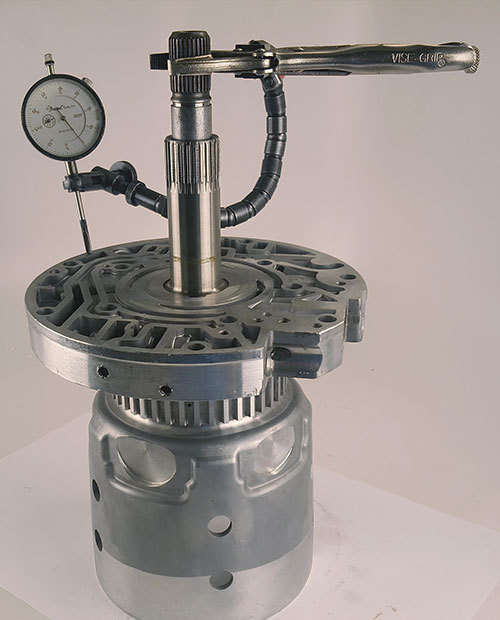
| Figure 5 — Use dial indicator to ensure stator is installed properly. |
|---|
 |
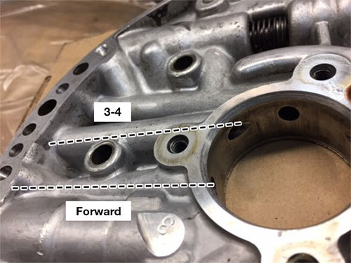
| Figure 6 — Test to detect cracks. |
|---|
 |
Since 3rd Gear oil is connected to forward and 2nd clutch circuits, we must eliminate leaks from the forward and 1-2 accumulator circuits. Oil commonly leaks past the pins due to wear created by high cycle rates, which can also wear the piston bore and cause the piston to cock in the accumulator bore. Solutions are available in the aftermarket that both eliminate the pin (and the leaks that go with it) and provide more piston stability.
The foundation of a good unit is a tight, leak-free valve body. Controlling leaks improves line pressure and conserves pump volume to be used where needed. It is common to find bore wear that allows pressure drop in critical areas, such as AFL and TCC regulator bores. All valves/bores listed below play a part in applying the 3-4 clutch pack and must be vacuum tested to determine if replacement or reconditioning is necessary. If you find several leak points, you can tool up to fix them yourself or simply purchase a remanufactured valve body.
In addition to vacuum testing these valves, the following are other common valve body problems to be on the lookout for.
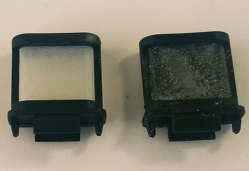
| Figure 7 — Dirty screens contribute to low line pressure. |
|---|
 |
While the 4L60/E family has reached the end of its production run, there are still millions of units out there that continue to accumulate miles, year after year. Much of the anxiety surrounding 3-4 clutch diagnosis stems from having an incomplete picture of the affected circuits and their components. That apprehension rapidly melts away in the face of a solid plan of attack based on a fuller understanding of those circuits, no matter how long and involved they are. Committing to a comprehensive diagnostic plan based on the road map laid out here — and following it every time you encounter 3-4 burn — is the key to keeping your sanity. Best of all, you’ll be able to confidently collect your fee and send your customers down the road with a long, reliable warranty.
Brian Wing is a Sonnax product development manager for driveline and transmission components. He is a member of the Sonnax TASC Force (Technical Automotive Specialties Committee), a group of recognized industry technical specialists, transmission rebuilders and Sonnax Industries Inc. technicians.
February 26, 2021
Gregg Nader
Required
Recommended
Required
Recommended
Required
Recommended
'88-Later
Required
Recommended
Required
Recommended
Wider than OE
Required
Recommended
Required
Recommended
4L60-E '97-earlier only, non-EC3 units
Required
Recommended
Fits all years & '98-later EC3 units
Required
Recommended
Required
Recommended
Required
Recommended
Required
Recommended
Required
Recommended
Fits '88-later units.
Required
Recommended
Required
Recommended
Required
Recommended
Required
Recommended
298mm Converter, reluctor style
Required
Recommended
280mm or 300mm Converter, non-reluctor style. '99-'04.
Required
Recommended
245mm or 298mm Converter, non-reluctor style, universal bolt pattern
Required
Recommended
Fits two locations
Required
Recommended
Required
Recommended
Fully compatible with '95-later with PWM/EC3 (electronically controlled capacity clutch) control.
Required
Recommended
Required
Recommended
Required
Recommended
Required
Recommended
Use with OE valve/bore only, addresses wear at inboard two spools & other locations.
Required
Recommended
Fits '07-later units.
While Sonnax makes every effort to ensure the accuracy of technical articles at time of publication, we assume no liability for inaccuracies or for information which may become outdated or obsolete over time.