March 26, 2020
Hydraulics Fundamentals Part VI: Converter Limit Valves
John Varvayanis
Read Part I , Part II, Part III, Part IV, Part V, Part VI, Part VII, Part VIII and Part IX of the Hydraulics Fundamentals series.
Shift valves have been around the automatic transmission world from day one. These types of valves are pretty much the gate keepers that connect line or clutch pressure to clutch apply and/or clutch exhaust circuits. Back in the day, these valves were controlled by governor circuits that would open and close the shift valve based on how fast the vehicle was moving down the road. In today’s transmissions, shift valves are typically controlled by ON/OFF shift solenoids and/or clutch pressures that are controlled by clutch pressure control solenoids.
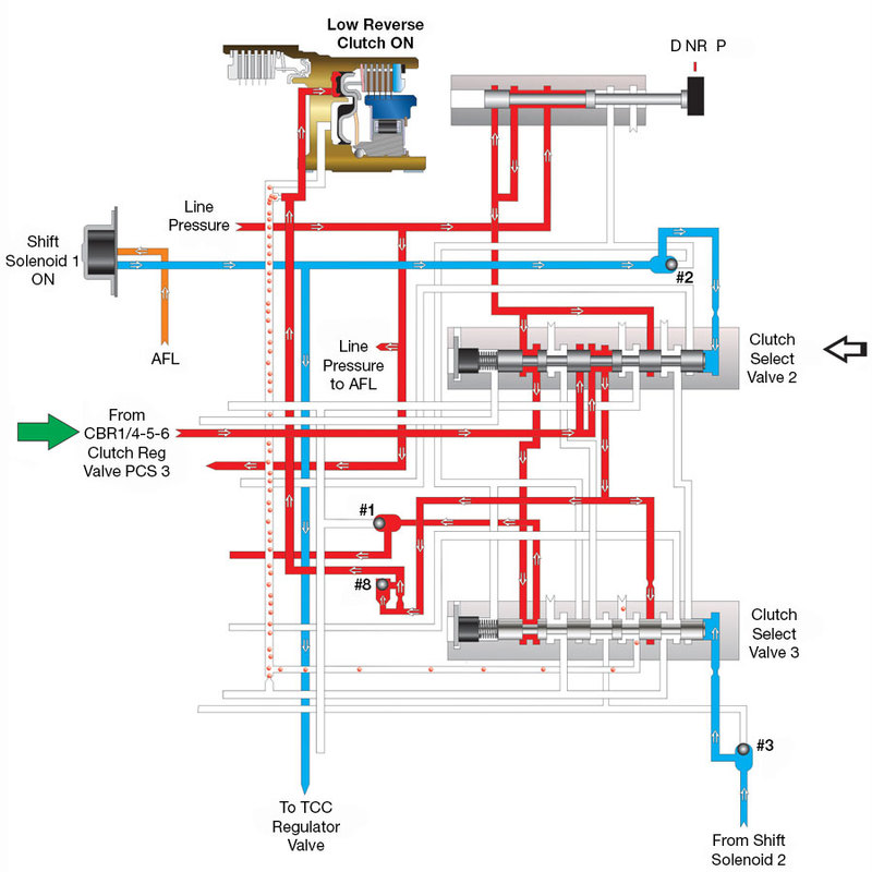
Figure 1 shows an example of typical shift valve function in today’s transmissions. The diagram shows the 6L80 engagement process into Drive 1st Gear from the Park position. Shift solenoid 1 — which is an ON/OFF solenoid — is turned ON, which strokes clutch select valve 2 to the left. This connects CBR1 pressure from pressure control solenoid 3 through clutch select valve 2 — which is functioning as a shift valve — to the low Reverse apply circuit. This connection provides a backup for the low sprag by the low Reverse clutch during launch in 1st Gear.
| Figure 1 – 2014-Later 6L80/90 1st Gear Engine Braking |
|---|
 |
| When the selector is placed into Drive from park/Neutral, 1st Gear is commanded and solenoid 1 is energized to provide engine braking. Clutch select valve 2 opens, connecting CBR1/4-5-6 clutch regulator pressure to the low Reverse apply passage. |
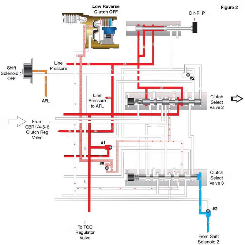
Figure 2 shows shift solenoid 1 turning OFF — this happens when vehicle speed is increased to a little less than 10 mph. When shift solenoid 1 is turned OFF, notice that clutch select valve 2 is moved back to the right by spring pressure. This provides an exhaust path to the low Reverse clutch and pressure from clutch pressure control solenoid 3 is decreased. So, in conclusion, shift valves of today are still the same — and have the same type of function — as earlier designs. In this instance, you can see that vehicle speed is a factor for low Reverse application in 1st Gear. The difference is that transmissions of today get vehicle speed information through electronic speed sensors, not through hydraulic governor pressure.
| Figure 2 – 2014-Later 6L80/90 1st Gear |
|---|
 |
| As vehicle speed increases, the TEHCM monitors information to determine when to turn solenoid 1 off and energize CBR1/4-5-6 solenoid to block pressure to clutch select valve 2. This action allows clutch select valve 2 to move to the right, connecting the low Reverse passage to an exhaust. |
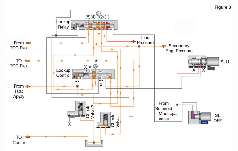
Relay valves have a very similar function to shift valves. The word “relay” means to receive and pass on, kind of like the old relay race baton hand-off back in the day in high school. Figure 3 shows a representation of the U760 transmission lockup relay valve in TCC OFF mode. When in this mode, the lockup relay valve receives line pressure to connection point number 1, which is blocked. Secondary regulator pressure is fed to connection point 3. The relay valve passes it along to the TCC release circuit to keep the torque converter clutch from applying and on to connection point A in the lockup control valve, which passes on this pressure back up to connection point 4 of the lockup relay valve, where it is blocked. Connection point 5 receives pressure from the TCC flex apply circuit, which is blocked by the valve. The TCC release circuit connects to the TCC apply circuit through the torque converter and is fed to connection point number 2, where it is sent off to the cooler.
| Figure 3 – TCC OFF |
|---|
 |
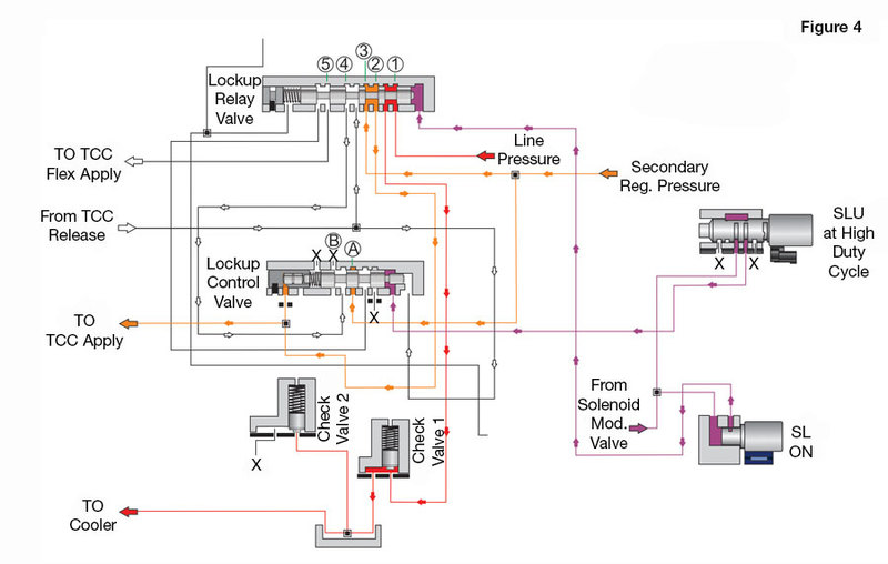
Figure 4 shows these valves when TCC is fully ON. The SL solenoid is turned ON by the powertrain control module, and the lockup relay valve strokes to the left. This action connects secondary regulator pressure from connection point 3 to the TCC apply circuit at connection point 2, which feeds apply pressure to the torque converter clutch. At the same time, TCC release pressure is connected to an exhaust path at connection point 4 at the lockup relay valve and is exhausted at connection point B at the lockup control valve, when the SLU solenoid strokes it to the left at high duty cycle. Connection point 1 at the lockup relay valve then connects the cooler circuit to line pressure to help cool the transmission.
| Figure 4 – TCC Fully ON |
|---|
 |
In conclusion, shift valves and relay valves share a lot of the same duties. Hopefully this information will help when diagnosing a shift or relay valve-related problem so you don’t drop the baton.
Jim Dial is a Sonnax technical specialist and a member of the Sonnax TASC Force (Technical Automotive Specialties Committee), a group of recognized industry technical specialists, transmission rebuilders and Sonnax Transmission Company technicians.
March 26, 2020
John Varvayanis
April 20, 2020
May 03, 2019
Bob Warnke
January 28, 2019
Zachary Richardson
February 26, 2019
Maura Stafford
March 26, 2019
Jim Dial
November 20, 2020
June 08, 2020
March 03, 2020
Jim Dial
While Sonnax makes every effort to ensure the accuracy of technical articles at time of publication, we assume no liability for inaccuracies or for information which may become outdated or obsolete over time.