December 07, 2016
A New Path for ZF
The ZF8HP45 and ZF8HP70 will soon be one of the newer transmissions coming out of OE warranty and entering your shops. This 8-speed RWD unit is used in numerous 2009-later BMWs, 2011-later Chrysler TH300s, 2015-later Dodge Challengers, 2012-later Dodge Chargers, Durangos, and Ram 1500 Pickups, 2011-later Jeep Grand Cherokees, as well as some Jaguars and Land Rovers. The ZF8HP45 is used in the V6 applications, while the higher torque ZF8HP70 is for the V8 engines.
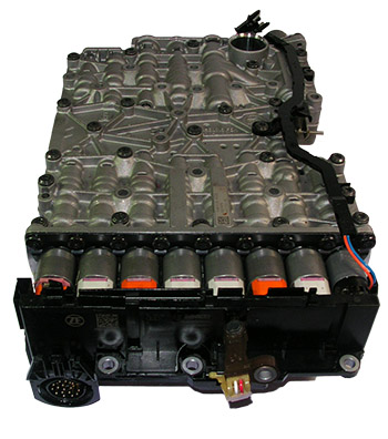
When looking at the valve body, the similarities to the 6-speed RWD ZF6HP19/26/32 and ZF6HP21/28/34 series are quite noticeable (Figure 1). The upper and lower casting halves are similar in shape and valve bore structure to the 6-speeds. The lower casting has a bank of eight familiar-looking orange- and new white-capped EDS solenoids. The upper casting houses the same problematic, rubber-tipped solenoid accumulators for the TCC, EPC and individual clutch/brake solenoids. Mounted on top is the plastic transmission control module assembly (TCMA) that houses the transmission control unit (TCU), input and output speed sensors, and the transmission temperature sensor.
| Figure 1 - ZF8HP45 |
|---|
 |
An examination of an oil circuit and individual valve lineups shows that this new ZF 8-speed uses the same type of clutch regulator and clutch holding valves to control fluid flow to the two brakes (A and B) and three clutches (C, D, E) that combine with the four planetary gear sets to achieve the nine gears: eight Forward, one Reverse (Figure 2).
| Figure 2 - 8-Speed Clutch Applications | |||||
| GEAR | Brake A | Brake B | Clutch C | Clutch D | Clutch E |
|---|---|---|---|---|---|
| 1st | ON | ON | ON | ||
| 2nd | ON | ON | ON | ||
| 3rd | ON | ON | ON | ||
| 4th | ON | ON | ON | ||
| 5th | ON | ON | ON | ||
| 6th | ON | ON | ON | ||
| 7th | ON | ON | ON | ||
| 8th | ON | ON | ON | ||
| R | ON | ON | ON | ||
Focusing in on the converter circuit is where a noticeable difference from previous ZF transmissions emerges. A new TC charge path has been added, making this a three-path converter circuit instead of the typical two-path circuit.
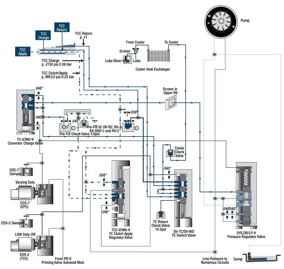
During converter release, the pressure regulator valve routes fluid pressure to the torque converter pressure valve, where it is regulated into converter charge pressure (Figure 3). Both of these valves are modulated by EDS-7 (EPC) solenoid pressure. This regulated charge pressure is routed to the converter through the torque converter switch valve, which also directs the return pressure out of the converter to the cooler and lube circuit. A portion of converter charge pressure is also orificed through the torque converter clutch valve and into the converter apply circuit.
| Figure 3 - ZF8 Converter Circuit Diagram, TCC Released |
|---|
 |
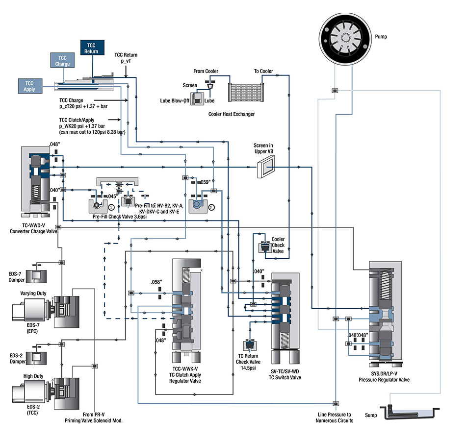
During converter apply, the EDS-2 (TCC) solenoid is energized, modulating both the TC switch valve and the TC clutch valve (Figure 4). This reroutes converter charge pressure directed to the TC switch valve to enter the cooler and lube circuit, and return pressure out of the converter is exhausted through the TC return check valve, with a minimum of 14.5 psi maintained in the converter. The TC clutch valve now routes regulated line pressure to the converter clutch apply circuit and the converter charge circuit. The converter clutch can be applied in any Forward gear from 1st through 8th.
| Figure 4 - ZF8 Converter Circuit Diagram, TCC Applied |
|---|
 |
| Valve | ZF Name | Chrysler Name |
|---|---|---|
| Pressure Regulator | SYS.DR-V | LP-V |
| TC Pressure | WD-V | TC-V |
| TC Switch | SV-WD | SV-TC |
| TC Clutch | WK-V | TCC-V |
All four of these valves in the converter circuit are controlled by variable force solenoids, so they are extremely busy and susceptible to wear. The pressure regulator valve is identical in function and design (although not size) to the commonly worn ZF 6-speed variety valve.
The TC switch valve is similar in design and function to the converter release regulator valve, which has been one of the most problematic valves in the ZF 6-speed units. The TC clutch valve is similar in function to the ZF 6-speed variety bypass clutch control valve, although designed like the ZF6 Gen. 2 clutch cooling valve, which is not used in the converter circuit. The 8-speed valve that is showing the most severe wear to date, however, is the TC pressure valve due to the EPC control and high activity.
Vacuum testing of the bores can be quickly and easily performed during any rebuild to ensure integrity of the converter circuits. Take advantage of the handy ZF8 valve body layout (see related tech resources) showing the various valves Sonnax has available to refurbish these valuable units. Plus, a free vacuum test guide will be available soon.
Learn More
Related Units
While Sonnax makes every effort to ensure the accuracy of technical articles at time of publication, we assume no liability for inaccuracies or for information which may become outdated or obsolete over time.