TF-81SC Solenoid Connector & Wire Color Identification
Valve Body Xpress
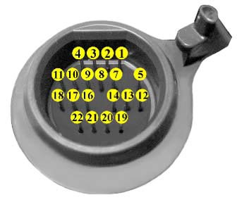
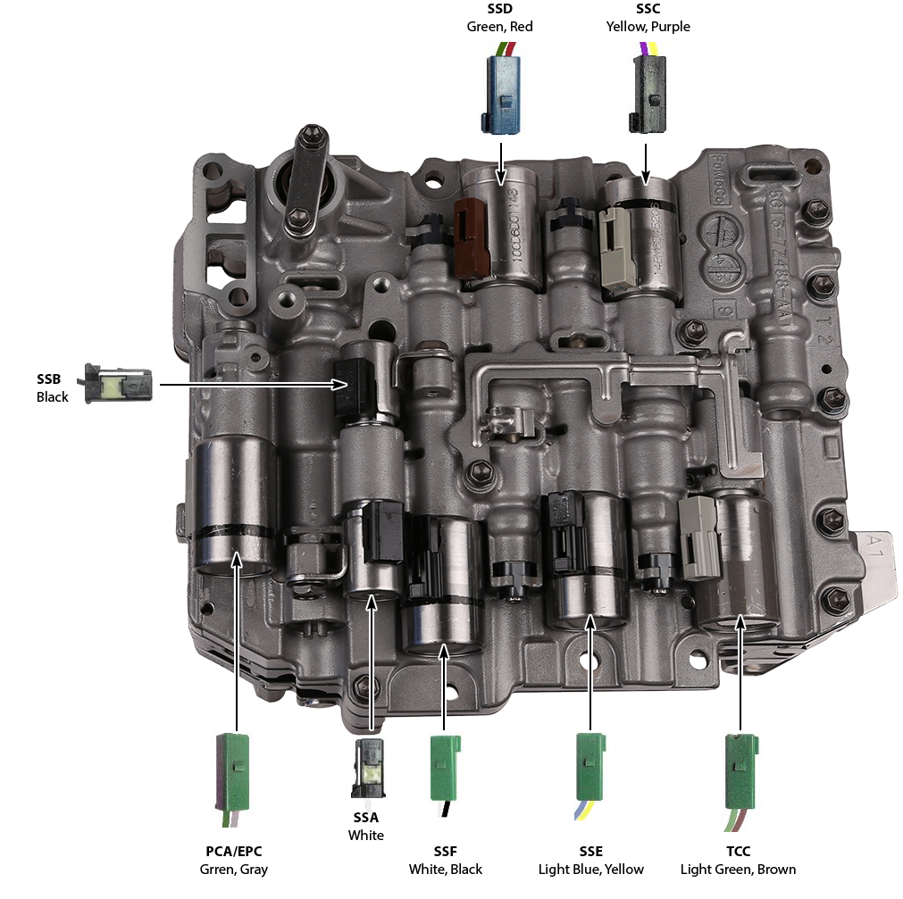
 Use the chart and connector diagram to check the solenoids from outside the transmission. Use the chart and valve body pictures to insure that the solenoids don't get cross-wired.

| Name | Positive Terminal (Wire Color) | Negative Terminal (Wire Color) | Harness Connector Color | Resistance (Ohms) |
|---|---|---|---|---|
| SSA | 5 (White) | Grounds to Case | Black | 11-15 |
| SSB | 2 (Black) | Grounds to Case | Black | 11-15 |
| SSC | 11 (Yellow) | 10 (Purple) | Blue or Black | 5.0-5.6 |
| SSD | 17 (Red) | 18 (Green) | Blue | 5.0-5.6 |
| SSE | 14 (Light Blue) | 22 (Yellow) | Green | 5.0-5.6 |
| SSF | 21 (White) | 16 (Black) | Green | 5.0-5.6 |
| TCC | 9 (Light Green) | 4 (Brown) | Green | 5.0-5.6 |
| PCA/EPC | 3 (Green) | 1 (Gray) | Green | 5.0-5.6 |
| TFT Sensor | 8 (Orange) | 7 (Orange) | Sensor is gray and part of internal harness | 77F-3.5K |
| TSS | 12 (White) | 13 (Red) | Tan | Hall Effect |
| OSS | 19 (Orange) | 20 (Blue) | Brown | Hall Effect |
Related Units
Related Parts
While Sonnax makes every effort to ensure the accuracy of technical articles at time of publication, we assume no liability for inaccuracies or for information which may become outdated or obsolete over time.